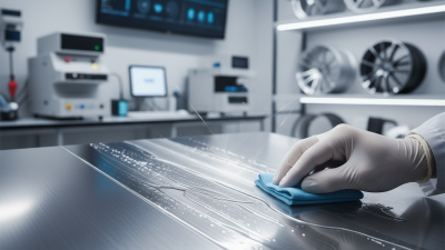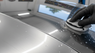
Ceramic Coating On Steel provides a durable barrier against heat, moisture, chemicals, abrasion, and surface corrosion. However, strong performance depends on preparation, product selection, and controlled curing. The coating cannot hide oil, loose scale, weld spatter, or poorly prepared edges. Preparation matters most.
This guide explains how experienced applicators prepare steel, select compatible ceramic products, and apply consistent coats. The process may involve degreasing, abrasive blasting, dust removal, and profile testing. A clean, slightly textured surface helps the coating bond properly. Small flaws show. Even a fingerprint can create a weak area.
Environmental conditions also matter. Temperature, humidity, ventilation, and substrate temperature should remain within the manufacturer’s specified range. Application tools must match the coating’s viscosity and recommended film thickness. Excess material may crack, sag, or cure unevenly. Too little may leave steel exposed. Measure twice.
A small test panel is a practical safeguard before coating a valuable component. It can reveal adhesion problems, color changes, pinholes, or unexpected curing behavior. Inspectors should record batch numbers, surface conditions, application times, and cure temperatures. These details support reliable quality control and make future troubleshooting easier. Results can still vary because steel chemistry, geometry, and service conditions differ. That limitation deserves attention. No single coating method suits every steel part, so technical data sheets and, when necessary, professional coating advice should guide the final procedure.
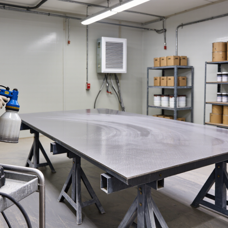
Ceramic coating is not one product. Sol-gel films usually form thin, dense barriers, often around 5–50 micrometres. Ceramic-filled polymers are thicker, commonly 100–300 micrometres. Thermal-sprayed ceramic systems may exceed 250 micrometres. These figures are practical ranges, not universal rules. The coating type must match temperature, abrasion, chemicals, and moisture exposure.
Prepare the steel to a near-white blast-cleaned condition, typically Sa 2½ under ISO 8501-1. Remove dust and salts before mixing or spraying. A clean surface matters more than a fashionable formulation. Measure surface profile and record temperature, humidity, and steel temperature. The steel should remain above the dew point, commonly by at least 3°C. Apply multiple controlled passes rather than one heavy layer. Excess thickness can trap solvents, crack, or reduce adhesion.
Film thickness should follow the coating’s technical data and service design. ASTM D7091 supports dry-film-thickness measurement using calibrated gauges. ISO 12944 defines durability bands from low, up to seven years, to very high, above 25 years. However, those periods depend on environment and maintenance, not coating thickness alone.
High-temperature service can also change the limit sharply. Some ceramic systems tolerate several hundred degrees Celsius, while others soften far earlier. This is where specifications often fail.
Test panels, cross-cut adhesion checks, and holiday inspection are worth the extra time. A perfect thickness reading cannot rescue poor surface preparation.
How to Apply Ceramic Coating on Steel?
Steel preparation decides whether a ceramic coating becomes protection or an expensive failure. The NACE IMPACT study estimated that corrosion costs about 3.4% of global GDP. That figure explains why surface verification deserves more attention than fast application. Inspectors should confirm SSPC-SP 10/NACE No. 2 cleanliness. At least 95% of each inspected area should appear free from visible oil, rust, mill scale, and old coatings. Remaining stains must be slight and firmly attached.
Dew-point control is equally critical. Measure air temperature, relative humidity, steel temperature, and dew point near the work area. The steel should remain at least 3°C above the dew point before blasting and throughout coating application. ISO 8502-4 provides practical guidance for assessing condensation risk. A cold steel plate can look dry while holding invisible moisture. That mistake is common. It is also costly.
Use calibrated instruments, not personal judgment. Record readings at several locations, especially near edges, welds, and shaded supports. Surface profile must match the ceramic system’s specification; ASTM D4417 methods can help verify it. Dust testing should follow the specified acceptance level before mixing materials. I have seen crews pass a visual check, then discover salt contamination beneath the coating. That is a useful warning: cleanliness is not the same as readiness. Recheck after delays, temperature changes, or visible condensation. Even experienced teams sometimes rush this step.
| Inspection or Application Stage | What to Verify or Do | Typical Acceptance Criterion | Recommended Method or Instrument | Record to Keep |
|---|---|---|---|---|
| 1. Steel Condition | Check the steel for oil, grease, salts, mill scale, rust, weld spatter, sharp edges, laminations, and other surface defects. | Contaminants and defects that could impair adhesion are removed or repaired before abrasive blasting. | Visual inspection, solvent-cleaning check, surface-defect inspection, and chloride or soluble-salt testing where contamination is suspected. | Initial condition, repairs required, contamination findings, and inspector name. |
| 2. Pre-Cleaning | Remove oil, grease, and other visible contaminants before abrasive blasting. Repair weld spatter, sharp projections, and rough edges as specified for the coating system. | The surface is visibly free of oil, grease, dirt, and loose contaminants before blasting. | Approved cleaning solvent or detergent process, lint-free wipes, scrapers, grinders, and visual inspection. | Cleaning procedure, repair areas, and verification results. |
| 3. Abrasive Blasting | Blast the steel to SSPC-SP 10/NACE No. 2, also known as a near-white metal blast cleaning condition. | At least 95% of each unit area is free of visible oil, grease, dust, mill scale, rust, coatings, oxides, corrosion products, and foreign matter. Light staining may remain on no more than 5% of each unit area. | Visual comparison with the applicable near-white blast-cleaning reference standard, supported by adequate lighting and magnification when needed. | Blast-cleaning standard, inspection areas, lighting conditions, and visual findings. |
| 4. Surface Profile | Measure the roughness created by abrasive blasting and compare it with the ceramic-coating manufacturer’s written specification. | The profile is within the coating specification; a common project range may be approximately 50–75 µm (2–3 mils), but the product data sheet governs. | Replica tape with a suitable micrometer, or a calibrated surface-profile gauge. | Profile readings, measurement locations, instrument identification, and calibration status. |
| 5. Dust Removal | Remove abrasive dust from the blasted surface using clean, dry, oil-free compressed air or an approved vacuum method. | Dust is removed to the project-specified cleanliness level, with no loose particles that could interfere with adhesion. | Visual inspection and a standardized dust-tape test when required by the specification. | Dust-test result, test locations, and corrective actions. |
| 6. Soluble Salts | Test for soluble ionic contamination when the steel has been exposed to marine, chemical, deicing-salt, or other corrosive environments. | The result is below the project or coating specification limit. No universal limit applies to every ceramic coating; the written coating specification controls. | Conductivity-based field extraction test or another validated soluble-salt test method. | Test method, extraction area, result, temperature, and acceptance limit. |
| 7. Climate Conditions | Measure air temperature, steel temperature, relative humidity, and dew point immediately before coating and at regular intervals during application. | Steel temperature remains at least 3°C above the calculated dew point throughout application and initial curing, unless the product specification requires a greater margin. | Calibrated psychrometer, digital thermo-hygrometer, or surface-temperature thermometer with dew-point calculation. | Air temperature, steel temperature, relative humidity, dew point, time, and location. |
| 8. Coating Window | Apply the ceramic coating before flash rust or visible recontamination develops, and within the product’s specified temperature and humidity range. | The surface remains clean, dry, and within the permitted environmental conditions from preparation through application. | Continuous or periodic environmental monitoring and visual inspection. | Environmental readings, start and stop times, and any weather-related interruptions. |
| 9. Mixing and Application | Mix components in the stated ratio and apply the coating using the approved spray, brush, or roller method. Observe the specified wet-film thickness and recoat interval. | Mix ratio, pot life, wet-film thickness, dry-film thickness, and recoat interval comply with the coating product data sheet. | Graduated mixing containers or approved mechanical mixer, wet-film comb, and calibrated dry-film-thickness gauge. | Batch identification, mix ratio, application method, pot life, film-thickness readings, and applicator. |
| 10. Final Inspection | Inspect the cured coating for runs, sags, pinholes, misses, holidays, cracking, blistering, poor coverage, and other visible defects. | The coating is continuous and defect-free, with dry-film thickness and repair areas meeting the project specification. | Visual inspection, calibrated dry-film-thickness gauge, and holiday detector when required by the coating system. | Final inspection report, thickness map, defect list, repairs, and acceptance sign-off. |
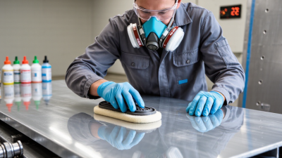
Abrasive blasting is the foundation of a durable ceramic coating on steel. I remove oil and grease before blasting. Otherwise, the abrasive can spread contamination across the surface. The steel should reach a 50–75 μm profile, measured with a calibrated profile gauge or replica tape. This texture provides mechanical grip without creating excessive peaks.
After blasting, I inspect the steel under bright, angled light. Rust stains, mill scale, and embedded abrasive must not remain. Clean, oil-free, dry compressed air removes loose dust. I then check for soluble salts, especially on steel exposed to seawater or road spray. A conductivity-based salt test can reveal contamination that looks invisible. If salt levels exceed the project specification, I wash, dry, and reblast or abrade as required. Do not rush this step.
Oil needs separate attention. I wipe small areas with a compatible solvent and replace dirty cloths often. Large surfaces may require approved detergent cleaning before final blasting. The steel must be visibly dry and free from fingerprints before coating. I have learned that “clean enough” is a risky judgment. Even a thin dust film can weaken adhesion. In practice, I overcheck corners and welds because these areas often fail first. The preparation feels slow. It prevents expensive rework. Apply the ceramic coating within the specified window, following the technical data sheet and site conditions.
The steel surface should be abrasive-blasted to a 50–75 μm surface profile. Before coating, remove visible dust, soluble salts, and oil contamination. Acceptance limits may vary by coating specification and project requirements.
The chart shows the specified blast-profile range and commonly used cleanliness control values: ISO 8502-3 dust rating up to Class 2, soluble salts below 50 mg/m² where that project limit is specified, and no detectable oil or grease contamination.
How to Apply Ceramic Coating on Steel?
Steel preparation controls the coating result. Remove oil, rust, salts, and loose mill scale before application. Abrasive blasting should create the profile required by the coating specification. ISO 8501-1 defines visual cleanliness grades, while ISO 8503 addresses surface profile comparators. Mix the ceramic coating exactly at the stated ratio. Scrape the container walls and bottom during mixing. Then record the start time. Pot life begins after the components meet. Higher temperatures usually shorten working time. Do not thin or reuse material after it becomes stringy. I have seen a smooth-looking batch fail because its pot life was already exceeded.
Apply controlled, even passes with a suitable roller, brush, or spray system. Build the specified 25–75 μm dry film thickness, not an improvised “thicker is safer” layer. Excess thickness can trap solvents, crack, or cure unevenly. ASTM D7091 describes nondestructive dry film measurement methods for metal substrates. ISO 19840 also provides guidance for verifying coating thickness on rough surfaces. Measure several points after curing, including edges and welds. A single reading proves very little. Record substrate temperature, air temperature, humidity, batch number, and measured DFT for traceability.
Tips: Mix smaller quantities when the work area is slow. Keep tools clean and ready before mixing. Check the coating’s pot-life clock, not just its appearance. Stop application if condensation approaches the steel temperature. Recheck thin spots after the first cure. This step can feel excessive, but missed welds often become the first visible defects.
After application, curing is not a waiting period to ignore. It is part of the coating system.
Keep the steel surface within the specified temperature and humidity range. Protect the coated area from dust, rain, condensation, and accidental contact. Cure time depends on film thickness, temperature, and ventilation. A surface may feel dry while remaining soft beneath.
Inspect the coating under bright, angled light. Look for pinholes, runs, dry spray, craters, exposed welds, and missed edges. Pay special attention to bolts and sharp corners.
Use a calibrated dry film thickness gauge on several steel areas, not just the easiest locations. Record the readings and compare them with the required range.
One high reading does not prove full protection. The first reading is not always the best reading.
Adhesion testing should be planned carefully because some methods damage the coating. Test only after the recommended cure period, using clean, representative areas. Record the test location, result, and failure pattern.
Holiday detection can find pinholes invisible to the eye, but excessive voltage may damage sound coating. Select the voltage according to coating thickness and technical instructions.
Repair every confirmed defect, then allow proper curing and repeat the inspection. This step is often rushed. That is where confidence can become misleading.
Before service, keep the inspection records with environmental readings, DFT results, adhesion findings, holiday results, and repair details.